Lets Explode a Few CB Myths
I'd like to preface this
discussion with a plain and simple truth about
CB'ers. Most CB'ers are clueless about radio
theory. The CB band is filled with average joes with no
formal electronics training trying to guess at radio
theory. As a result, nonsense CB folklore has
filled the airways for decades. If you actually
start cracking the radio theory books and start learning
legitimate radio theory you will be quickly outnumbered by
CB'ers who have no clue what they are talking about.
They will argue with you until hell freezes over, and
they will be wrong the whole time. Accept it. The
more you learn legitimate radio theory the more you will
be outnumbered by the clueless CB masses.
If you actually want to start
separating radio fact from CB radio nonsense start
reading the ARRL amateur radio license manuals.
Even if you are not interested in getting your ham
license the ARRL license training manuals are a radio
theory gold mine. What works on ham radio works on
CB radio although you will need to resize the amateur
radio antenna designs for 27 MHz.
Now lets get to some CB myth
busting.
1) My transmit sounds distorted locally, but it clears up when the signal gets further out.
Unless the person you are talking to over the CB is sitting a few feet from you this is not correct. If you start with a distorted signal you end with a distorted signal. The atmosphere does not work miracles on your CB signal to clean up distorted transmit audio. Unless the receiver is within "rock throwing distance" of the transmitting antenna, if it sounds distorted locally it will sound distorted out in the distance.
2) My two pill amplifier with two 2879 pills will dead key 400 watts and modulate 800 watts.
Guess again, and stop using those lying Dosy and Paradynamics meters.
First they are not "pills". They are transistors. Toshiba's 2sc2879/2sc2879a transistors are rated at 100 watts PEP each. Not 150 watts PEP. Not 200 watts PEP. 100 watts PEP! If you overdrive them you or over voltage them you will eventually blow them. Toshiba's datasheet for their 2sc2879a transistors in Adobe Acrobat format can be viewed by clicking here. Most CB amp manufacturers are not telling the truth. Toshiba is. If your meter agrees with the vendors exaggerated claims get another meter.
So what what kind of output should you expect from an amplifier with two properly set up 2sc2869 transistors in class AB operation? Assuming the transmitter is set up to run the transistors at their maximum rated settings and the power supply can deliver the required DC power input;
AM double sideband = About 70
watts carrier max with clean undistorted modulation, but
it going to run hot.
SSB (LSB and USB) = 200 watts PEP
Many of the better amateur radio transmitters use two 2sc2879 transistors to "loaf along" at 100 watts output on sideband. The lower output is designed to promote long service life and clean transmit signals.
3) A rejection kit will improve the performance of my beam.
Wrong. The rejection kit being sold for various beams is pure snake oil, and it goes against accepted antenna theory. It will degrade the performance of your beam. Signal Engineering has a great web page blowing holes in the "CB Antenna Rejection Kit" scam at http://www.cbantennaguide.com/Hybrid.htm
4) To get out you need lots of swing in your AM signal.
Wrong. An AM signal is fully modulated when the "swing" doubles the carrier. That is to reach 100% modulation a 4 watt key should swing no more than 8 watts. Anything more than that is distortion to your voice. The AM carrier is necessary for the receiver to properly demodulate the audio from the signal. If you add excessive swing it will distort your audio. It will not help you get out better.
If you really want to see the needle swing when you talk purchase a sideband capable radio. Sideband is a much more efficient means of transmitting. You will be able to talk much further with alot less power. The signal to noise ratio on sideband is much better than AM which means you should be able to hear weak signals better on sideband than on AM.
5) The myth of CB AM swing.
What most CB operators do not know is that AM modulation does not just swing forward. It also swings backwards. The reason a watt meter only shows the forward swing is because the watt mater contains something called a diode. The RF signal from the transmitter is passed through the diode before it gets to the actual needle on the watt meter. The diode only allows electricity to flow in one direction, so the meter only sees the positive half of the "swing". If the diode was not in place the meter would not work correctly, because the needle could not possibly move fast enough in the positive and negative directions to show the RF signal in it's true state.
Just know this. Ecessive "swing" that far exceeds the carrier equals distortion. It does not make you get about better, but it does cause more co-channeling to those on the other end.The formula for calculating percentage of modulation is;
% of modulation = (A - B) / ( A + B ) * 100
A = peak to peak
B = unmodulated carrier
Unfortunately you will need a oscilloscope to use that formula, because the watt meter does not show an accurate picture of what is really going on.
6) Pouring salt in the ground around the base of your antenna will help you get out better.
Pouring salt in the ground will increase the soil conductivity in the immediate area of the antenna, but you would have to saturate the ground surrounding the antenna with salt for hundreds of yards to make any noticeable difference. There are many papers on this subject, so I'll just keep my answer short and to the point. The higher your antenna is above ground the less influence near field ground loss will affect your signal. If you can get the base of your CB antenna 75 feet or more above ground (about 2 wavelengths at 27 MHz), pouring salt in the ground around the antenna will not make any difference. At 36 feet the difference if any will be so small no one will notice.
If the base of the antenna is on the ground then near field ground losses will be significant. Burying a large number of 1/4 wave ground radials around the base of the antenna will help your transmission in this instance, but you will get a much bigger bang for the buck on the CB band by raising your antenna as high possible. A 5/8 wave ground plane antenna with the base of the antenna starting at 72 feet is an amazing performer on the CB band.
7) Exaggerated antenna gain claims for single element omni directional antennas.
On the 27 MHz CB band, the taller a vertical omni directional antenna the higher the gain up to about 23 feet.* After 23 feet the gain of the antenna begins to decrease. There is no magic bullet to escape this rule. The highest real gain omni-directional CB antennas currently on the market are the full length 5/8 wave and .64 wave antennas. 1/2 antennas have less gain than 5/8 wave and .64 wave antennas, and 1/4 wave antennas have less gain than .64 wave, 5/8 wave, and 1/2 wave antennas.
5/8 wave and .64 wave antennas also have a much lower angle of radiation than 1/2 wave and 1/4 wave antennas. A low angle of radiation really pays off when trying to talk to distance skip station in excess of 1500 miles.
On the 27 MHz CB band a high angle of radiation (30 degrees above the horizon) such as a that offered by a horizontal 1/2 wave dipole about 18 to 32 feet off the ground may actually out perform a .64 or 5/8 wave vertical antenna when talking skip to stations closer than 1000 miles, but the 5/8 and .64 wave antennas will be the clear winner when talking skip to stations more than 1500 miles away.
I'll may post a more detailed essay on the angle of radiation at a later date. Just know that the best antenna for talking skip to stations over 2000 miles away is not necessarily the best antenna for talking skip to stations closer than 1000 miles. An antenna with a low angle of radiation is always the superior performer locally (non-skip).
Below is a quick analysis of some common omni-directional CB antennas.
-
Solarcon Max 2000 (also called I-Max 2000) = .64 wave antenna
-
Shakespear NBS-2010 Base Antenna = 5/8 wave antenna
-
Solarcon A99 = 1/2 wave antenna
-
Solarcon I-Max-99 = 1/2 wave antenna
-
Shakespear 176-GBS 18' Super Big Stick = 1/2 wave antenna
-
Antron 99 = 1/2 wave antenna **
-
Star Duster = 1/4 wave ground plane antenna
-
Astroplane = 1/4 antenna or slightly longer, but not a 1/2 wave
-
SkyLab T233 10 Meter Commercial Base Antenna = 1/4 wave ground plane
-
Maco 5/8 wave ground plane***
- Hy-Gain Super Penetrator - 5/8th wave ground plane < == I
recommend this antenna!
** The Antron 99 claims to be a 1/2 wave over a 1/4 wave antenna, and it is. What they do not tell you is the bottom 1/4 wave section is for matching purposes only, and only the top 1/2 wave section radiates any appreciable power. For gain comparisons consider it a 1/2 wave antenna.
*** The Maco 5/8 wave ground plane antenna is not a true 5/8 wave antenna on 27 MHz. It is only about 20 feet long, but it should out perform a 1/2 wave antenna or a 1/4 wave antenna. The four aluminum ground radials should give it better isolation against near field ground losses when the antenna is less than a 36 feet off the ground than a "big stick" style antenna without a radial kit.
The half wave dipole is considered to be the legitimate engineering standard for gain comparison. A "5.0 dbd gain" claim means 5 db gain over a 1/2 wave dipole. If the gain just says "db" gain they are not telling you what the antenna has gain over. For all you know it could be gain over a radio with no antenna plugged up.
"dbi" means gain over an isotropic antenna. An isotropic antenna radiates equally in all directions including up, down, diagonal, and everything in between. An isotropic antenna is an antenna that exist only in theory. A 1/2 wave dipole is a real antenna, and it is the preferred measuring stick by which legitimate antenna measurements are made.
The best way to avoid being fooled is to measure the vertical antenna element.
On the 27 MHz CB band;
.64 wave = about 23 feet (BEST GAIN - about 1.5 dbd gain)
5/8 wave = about 21 feet (VERY CLOSE SECOND BEST - about
1.2 dbd)
1/2 wave = about 17 feet (AVERAGE - ZERO gain dbd)
1/4 wave = about 8 feet 7 inches (BELOW AVERAGE -
1.5 dbd LOSS!)
* It is possible to build an omni-directional antenna taller than 23 feet with higher gain, but it involves stacking half wave vertical elements on top of each other with phase reversal stubs. It is possible, but mechanically challenging. To date I have not seen any commercial CB antennas that employ stacking vertical elements to obtain higher gain on the CB band. I have seen it done on the higher VHF frequencies where antenna size is smaller.
8) Trimming the length of my coax will lower my SWR.
Wrong. Trimming the length of your coax will trick your SWR meter and you in to believing your SWR is lower. SWR is the ratio of the impedance of your coax to the impedance of the antenna. Standard CB coax is rated at 50 ohms. It has a 50 ohm impedance regardless of whether it is 3 feet long or 1000 feet long. To get a Standing Wave Ration of "1 : 1" both the antenna and the coax must have an impedance of 50 ohms. If the antenna has an impedance of 100 ohms and the coax has an impedance of 50 ohms then your SWR is 2:1, or put another way the impedance of the antenna is twice the impedance of the coax. Likewise an antenna impedance of 25 ohms and a coax impedance of 50 ohms is STILL a 2:1 SWR because the coax impedance is twice the impedance of the antenna.
Changing the length of the coax will neither change the impedance of the coax, nor will it change the impedance of the antenna. It will trick your SWR meter in to a false reading. In reality the impedance mismatch between the antenna and the coax will remain, and so will the accompanying power loss. It does not matter whether you have a Bird SWR meter or a Radio Shack SWR meter. SWR meters are not perfect, and they can be fooled.
If you can change the SWR reading on your SWR meter by changing the length of the coax then you can be sure of only one thing. You do not have a 1:1 impedance match between your antenna and your coax. This discussion does not apply to ladderline/coax matching sections at the antenna.
Signal Engineering has a more detailed explanation of coax and various CB myths on-line at http://www.cbantennaguide.com/Coax_Basics.htm
9) You can increase the receive and transmit of your fiberglass base antenna by changing the top whip to a steel whip.
Wrong. Changing the whip might ever so slightly change the electrical length of the antenna, but the change will be so small it will not amount to anything you or your CB friends will notice.
Fiberglass coated antennas have two advantages over aluminum tubing antennas;
1) The SWR on a fiberglass coated antenna is less affected by the presence of rain or ice.
2) If a fiberglass coated antenna falls across a power line you are less likely to receive an electrical shock. Notice I said "less likely". Do not assume it means you will never get shocked.
10) An echo box will make you get out better.
No it won't, but it will mark you as a "CB newbie" in the eyes of more knowledgeable and experienced operators.
11) The total length of your coax should be a multiple of 25 feet.
There is no technical basis for cutting the total coax length to a multiple of 25 feet.
12) The mobile beam antenna (laugh).
Star Gun Mobile Beam Antenna
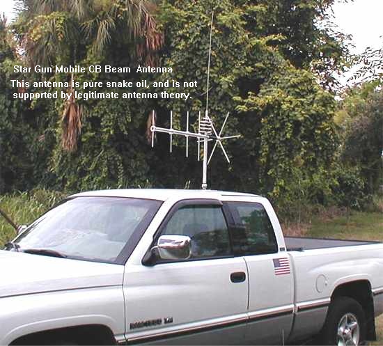
Some bozo
is selling a CB mobile beam antenna. He either lacks a
solid understanding of accepted antenna theory, or he is
out to make a quick buck off the gullible. In either case
this mobile CB beam antenna is pure non-sense, and is not
supported by accepted antenna theory. It might make a nice
coat rack though. If anyone tries to tell you this is a
legitimate CB beam ignore them. They have just verified
they are clueless about antenna theory.
13) Whistling in your mic is bad for the tubes in an RF amplifier.
Not really, but tuning up your amplifier ten times a day is. If you repeatedly whistled for long durations of time you may shorten the life of your amps tubes, but one quick whistle should not hurt a thing provided you are not over driving your amp.
14) A CB with a digital display does not get out as good as a CB with a plastic channel selector with the numbers printed on it.
Wrong. How the channel number is displayed has nothing to do with how well a radio will get out.
15) Old 23 channel CB's get out better than 40 channel CB's.
The number of channels has nothing to do with how well the radio will get out. There are some 40 channel CB's that will out perform some 23 channel CBs, and there are some 23 channel CB's that will out perform some 40 channel CB's.
16) If you co-channel other people alot it means you are getting out good.
Wrong. Actually the opposite is true. Assuming the output wattage is the same, a dirty signal is wasting power on frequencies other than the one you are listening to. A clean signal concentrates it's RF output on the channel you are using. Think of your RF output like a flashlight at night. If the light goes out in all directions the light in the direction you need it in is dimmer, but if you concentrate the light into a tight beam in the direction you need it then the light gets brighter. Why waste your output power on channels you are not even listening to?
17) Wide band audio on AM. One of the current trends by some operators is to try to expand the transmit audio frequency response beyond 3 kHz on the CB band. This is pretty much a waste of time on the CB band for the following reasons;
- CB radios typically have an audio frequency response
of up to about 2.7 kHz. Any received audio
frequencies above 3 kHz get shaved off by the CB
receiver. That means transmitting audio frequencies
above 3 kHz is a complete waste of time since most CB
radios will never reproduce it.
- The bandwidth of an AM signal is twice the highest audio frequency assuming the AM signal is not over modulated (Gee that never happens on the CB band). CB channels were designed so that a 6 kHz wide AM signal would have 2kHz of "buffer zone" on each side of the AM signal before the next channel begins. Expanding the upper frequency response just causes unnecessary bleedover to the next channels.
18) Bird watt meters with peak reading kits! Now this takes the cake. Some CB'ers go out and pay the extra money to buy a Bird 43 watt meter, but when it tells them the truth and hurts their feelings they install a peak reading kit to make it lie like a Dosy. Accept the truth! Your 2 or 4 or 1 driving 4 transistor amp does not put out 1200 watts (or whatever your lying Dosy meter says it does), and your two 3-500zg tubes do not put out 3000 watts. But ...but ....but... it's Bird watts?! The legitimacy of "Bird watts" went out the window when the peak reading kit was installed.